 |
||
 |
||
 |
||
 |
||
 |
||
 |
||
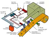 The Fife tension reel guiding system assures evenly
wound coils by automatically aligning the coiler with the
edge of the winding strip. The sensor (A) is rigidly
attached to the recoiler, and both move laterally in unison.
An optional system is available in which the sensor (B) is
electronically connected to the recoiler.
"Remote Positioning," "Centering." "Seek," and
"Staggerwind" features are available to further automate the
setup and coil winding pattern requirements.
The Fife tension reel guiding system assures evenly
wound coils by automatically aligning the coiler with the
edge of the winding strip. The sensor (A) is rigidly
attached to the recoiler, and both move laterally in unison.
An optional system is available in which the sensor (B) is
electronically connected to the recoiler.
"Remote Positioning," "Centering." "Seek," and
"Staggerwind" features are available to further automate the
setup and coil winding pattern requirements.
| |
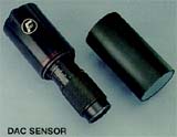 This digital sensor is virtually unaffected by contaminants
or heat. Suitable for recoiler guiding and guiding inside
ovens through windows.
A line detecting, high-resolution diode array camera, this
sensor has an array of 2,048 pixels to detect contrast
changes in its field of view.
The camera has a zoom lens which can be easily
adjusted and focused for different applications within its
range. Exposure time is automatically adjusted depending
on conditions.
It's protected to IP67 (DIN40050) and can operate in
ambient conditions up to 50oC. 125oF. The camera is
totally enclosed in an aluminum housing and the lens
system is protected by a glass filter.
This digital sensor is virtually unaffected by contaminants
or heat. Suitable for recoiler guiding and guiding inside
ovens through windows.
A line detecting, high-resolution diode array camera, this
sensor has an array of 2,048 pixels to detect contrast
changes in its field of view.
The camera has a zoom lens which can be easily
adjusted and focused for different applications within its
range. Exposure time is automatically adjusted depending
on conditions.
It's protected to IP67 (DIN40050) and can operate in
ambient conditions up to 50oC. 125oF. The camera is
totally enclosed in an aluminum housing and the lens
system is protected by a glass filter.
| |
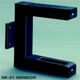 This transmitted-light sensor is unaffected by ambient light
or contaminated conditions. Suitable for coiler and
intermediate guiding applications and where solvents or
other chemicals are present.
The Fife S3-21 Transmitted-Light Sensor measures the
lateral position of the strip using infrared diodes pulsed at
50kHz. The sensor consists of two channels-a reference
channel to eliminate distortion from contamination and a
guide channel which senses the strip edge. The light
signals from both reference and guide channels are
processed by demodulation and filter circuits so ambient
light is filtered out.
This transmitted-light sensor is unaffected by ambient light
or contaminated conditions. Suitable for coiler and
intermediate guiding applications and where solvents or
other chemicals are present.
The Fife S3-21 Transmitted-Light Sensor measures the
lateral position of the strip using infrared diodes pulsed at
50kHz. The sensor consists of two channels-a reference
channel to eliminate distortion from contamination and a
guide channel which senses the strip edge. The light
signals from both reference and guide channels are
processed by demodulation and filter circuits so ambient
light is filtered out.
| |
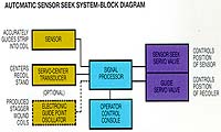
 The Fife seek system of recoil guiding increases production with fully automatic sensor alignment, locking, and guiding modes. The operator never touches any guiding controls throughout the entire sequence. A number of less sophisticated versions are available on request. The "seek" systems utilize the Fife A6, A7, CDP, or FLC Signal Processors. | |
|
(ASSUME: Strip is being wound on coiler mandrel.) 1. Edge sensor automatically positions recoiler to strip edge. 2. Operator shears strip. 3. Strip end detector (usually customer-supplied) sensing sheared end, locks recoiler in position. 4. Operator removes coil. 5. Recoiler remains locked while coil is removed; then recoiler centers. 6. New strip moves toward sensor. 7. Sensor automatically seeks strip edge and locks on as strip continues to move toward recoiler. NOTE : 50 milli-seconds after sensor is locked onto strip edge, the recoiler guiding system is in the automatic mode; " Auto On" indicating light signals the operator. 8. Operator feeds new strip onto recoiler and builds up tension and speed. This is one example. Other sequences of operation are available with the other processors. | |
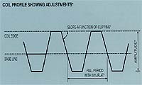
| Another optional circuit system is an electronic guide point oscillator system for achieving "stagger wound" coils. Electronically shifting the sensor guide point produces stable, easily handled coils. Period, amplitude, and wave form clipping adjustments can be easily and independently made. | |
|
- No mechanical parts to wear out (such as relays or limit switches) - Digital logic shifts sensor guide point - Fully adjustable stagger wound coil buildup - Consistent, repeatable wave form throughout entire coil |