|
||
 |
||
 |
||
 |
||
 |
||
 |
||
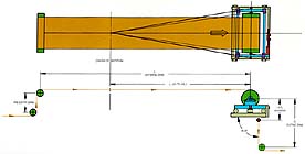
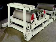
The Fife heavy-duty Kamberoller steering guide assembly is used for guiding installations at the end of long free spans where "off-tracking" most frequently occurs. The induced stresses from lateral bending of the strip in the entry span are held below permanent deformation levels through proper selection of the span length. The exit span is perpendicular to the plane of guide motion and relatively short as the strip undergoes a slightly helical rotation. To maintain low induced stress levels from the guiding action, both entering and exiting span required lengths are calculated on the basis of application parameters, amount of expected error, and material characteristics. The steering effect in the entry span, caused by angular and lateral guide motion, prealigns the strip, preventing damage to oven walls, pass line openings, and the strip. This feature is a prime advantage for the Kamberoller steering guide, as in many cases the strip would not otherwise traverse the entire length of a long span without damage. Proper application of Kamberoller steering guides permits higher machine speeds without manual attention to strip position, assuring increased productivity. The required entering span and correction capacity of a steering guide can be determined using the following formulas: | ||
| ||
The Fife Kamberoller steering guide is applied at the end of long, free strip spans. When error begins to occur in the strip lateral position, instantaneous movement of the Kamberoller steering guide makes immediate lateral correction, while the simultaneous swiveling action compensates for the tendency of the strip to go off to the right or left. A Kamberoller steering guide utilizes angularly adjustable raceways to permit any field adjustment necessary to satisfy actual operating conditions. Long catenary spans (such as through a paint oven) require special considerations at the guide to assure good tracking through the oven and quench, as well as adequate correcting ability. The point about which the guide assembly rotates in reaching the angular position required for a given correction is the "center of rotation." When the center of rotation is properly located, the roll displaces the material instantaneously when making corrections. Generally, locating the center of rotation of the Kamberoller steering guide from 2/3's to 3/4's of the entering span length ahead of the guide roll will assure satisfactory, dynamic performance. | ||
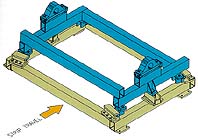
- High - strength "through-bolt" construction - Heavy - duty cam track support at all four corners - Double clevis - style cylinder mounted for easy access - Integral Servo - Center transducer mounting available - Several styles and sizes available to suit application and load, and to accept customers' rolls - Mechanical locking pins - Mechanical or electrical stroke indicators available | ||
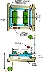
 This displacement-type guide is specifically designed for
metals applications involving short spans or limited
space. Correction(±C) is made by displacing the strip
angularly through the span of the guide.
Fife heavy-duty offset pivot guide assemblies are
designed to meet specific strip guiding requirements. To
optimize guiding results, information is necessary on
actual material, running tensions, expected error, rate of
error, width and thickness of material, and modulus of
elasticity. To determine the entry and exit spans of an
offset pivot guide, the following formula is used:
This displacement-type guide is specifically designed for
metals applications involving short spans or limited
space. Correction(±C) is made by displacing the strip
angularly through the span of the guide.
Fife heavy-duty offset pivot guide assemblies are
designed to meet specific strip guiding requirements. To
optimize guiding results, information is necessary on
actual material, running tensions, expected error, rate of
error, width and thickness of material, and modulus of
elasticity. To determine the entry and exit spans of an
offset pivot guide, the following formula is used:
| ||
|
The offset pivot guide assembly can be centered, locked, or manually positioned to facilitate setup operations, emergency stops, and width changes. Application assistance is available from Fife to assure proper selection and installation of the guiding system best suited to meet your specific strip guiding requirements. | ||
- High - strength "through-bolt" construction - Heavy - duty cam track support at all four corners - Double clevis - style cylinder mounted for easy access - Integral Servo - Center transducer mounting available - Several styles and sizes available to suit application and load, and to accept customers' rolls - Mechanical locking pins - Mechanical or electrical stroke indicators available | ||
Fife electrohydraulic power units for intermediate guiding are designed for dependable service with minimum maintenance to power Fife guiding systems under continuous operation. A high-resolution, spool-type servo valve provides precise, proportional control. These power units are designed for use with all Fife metals system sensors. They feature modular construction with subplate-mounted components. Flange mounting of the motor minimizes pump-coupling-motor shaft misalignment problems. In selecting the proper model for a specific guiding application, consideration must be given to shifting speed, load, and hydraulic cylinder size. The proportional spool-type servo valve is highly efficient with low hydraulic power losses, assuring minimum operating costs relative to other type valves. Fife electrohydraulic power units can be furnished with one, two, or three servo valves to control up to three guiding systems simultaneously or independently. | ||
- Extremely rugged and reliable - Lower power consumption, single power source - Compact, completely self-contained - Electric motors are TEFC, with "life" lubrication - External nonbypass 2-micron, full-flow supply filter - Easily installed - can be mounted in any convenient location - Complete range of sizes - Minimum maintenance - Optional standby motor-pump modules | ||
Fife center guide sensors, generally used for intermediate guiding applications, are compatible with the full range of Fife power units, and can also be used for center guiding at uncoilers and recoilers. | ||
- Fully proportional - Fixed wide - angle photocells - High-intensity, continuous, fluorescent light source - Single guide point setting for all strip widths specified - Regulated lamp voltage supply available for improved accuracy - Rugged dust-tight and oil-tight housing - Guide point positioners available for manual or remote operation | ||
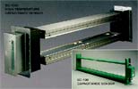
Fife's patented capacitance sensor is shielded to prevent interference from the external environment. It is virtually maintenance-free because it has no parts to wear out, such as light sources or optics. It is unaffected by ambient light, magnetic fields, or dust. The capacitance sensor requires no operator attention since no cleaning is necessary. | ||
Suitable for most intermediate center guiding applications, including: - High temperature - when temperatures exceed 250��, such as the heating sections of annealing processes. - Hostile environments - where dust or ambient light is present. - Inaccessible locations - ideal for top or bottom of vertical loopers or loop cars. ��Requires less space than optical-type sensors. | ||
- Virtually maintenance-free - Effective in hostile environments such as: 1) dust or other dry deposits 2) extreme temperatures up to 1800oF 3) gasses, such as furnace atmospheres 4) extreme ambient light 5) magnetic fields 6) wavy edges, plane changes, or twisting of strip | ||
Fife's SC-100 Capacitance Sensor measures the lateral position of metal or metalized strips in center guiding systems. The sensor consists of sending and receiving electrodes positioned above and below the strip. These electrodes are mounted in a heavy-dust, steel O-frame. AC voltage applied to the sending electrodes creates an electrical field between the sending and receiver electrodes. Depending on the lateral position of the strip, different levels of absorption of the electrical field are recorded by the receiving electrodes. This data is demodulated and transferred to the signal processor which directs a proportional signal to move the guide structure, correcting the strip position. The demodulation electronics are mounted in the sensor or close to it. The circuitry is designed to drive the electrodes at a low voltage level which is not dangerous. A lockout circuit is activated if the receiver electrodes are influenced by an outside signal. |
 |